Going Forward...
In my proposal for Synthesis and Resolution, I expressed that I want to develop my work from Unit X, working on my refinement, functionality and creating designs more unique to me. I want to continue with developing Filigree and Plique à Jour within my work. As well as this, as my final piece, I want to create a Brooch, Ring and a Headpiece as a collection for the degree show and, hopefully, New Designers. I made a mood board with all my previous and new research to help with visualising and developing my work.

Moodboard made by me
Technical Development
After reflecting on one of the Unit X Final pieces, I know I needed to develop the technical aspect of the Plique à Jour design I created. Traditionally, Plique à Jour cells are rounded and smooth. However, in my designs, the cells are cracks which involve sharp corners. This means the Plique à jour was bound to crack and potentially fall out of the cells and is not wearable.
The cracks came to me naturally when I was thinking about the design in the workshop and how I could incorporate my feelings into it. My initial concept for Unit X was to have a solid exterior to the front of the brooch, followed by a delicate piece at the back of the brooch as a representation of my situation, combined with influences from both sides of my heritage. This wasn't how the piece developed in the end, however, the cracks came as another aspect of my situation, as throughout my life, there were clues and 'cracks' with information I knew and how I am as a person, which make sense now I know about my heritage.
Because of this, my first test pieces this semester were to test four different designs. Two had wider cracks, and two had thinner cracks. I also decided to test two of these as flat pieces and two as curved pieces. In addition to this, I used a needle file and sandpaper to round off some of the sharp corners.

Design drawn with Sharpie

Pierced out

Starting to fill cells

Starting to fill cells

Flat pieces partly filled

Curved pieces partly filled

Flat pieces finised on paper

Flat pieces finished held upto the light

Finished curved pieces
After testing these Plique à Jour pieces, I found that the flat ones are less likely to crack and are easier for me to clean up, resulting in a more refined finish in comparison to the curved pieces, which had more cracks on the enamel due to the tension and are a lot harder to clean up. As a result of these tests, I decided to incorporate a flat piece for the Plique à Jour into my design. However, I need to carry on testing to make sure I can get it with no cracks in the enamel. In addition to this, I want to test the mixing of colours.
Sketches
I drew some sketches of ideas for the Brooch. A quality about brooches which I like is that the view of the Brooch from the eyes of the wearer is different to the eyes of the viewer. I want to play on this idea and have a filigree piece behind the Brooch, which only the wearer knows is there/can see. This concept is a reflection of my life and the feelings around finding out about my heritage, not so long ago. This concept carried on from Unit X. However, this time I have hope that I could develop this idea further. Below are sketches of ideas of how I can incorporate this context into my work.

Circle and square brooch ideas

Pin Ideas including adding filigree piece behind

Pin Ideas including adding filigree piece behind

More pin sketches
As previously mentioned, I wanted to create a ring as well as a Brooch and headpiece. Whilst at work, I was thinking about design ideas for this and made this paper sample. This design involves a gemstone and for the structure to be made out of filigree.

Ring paper sample

Ring paper sample
Research
Maps of Manchester & Iran
I decided I want to have more influence of Manchester in my work, as this is where I grew up and is a big part of who I am as a person today. I decided to look at maps and the outline of the areas.
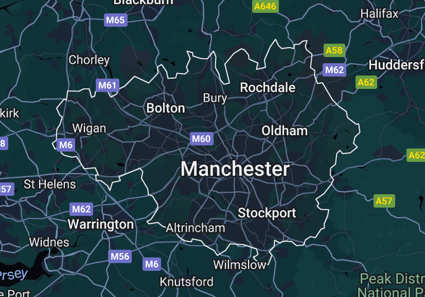
Outline of Greater Manchester area

Outline of main area of Manchester
I looked into more detail of this and looked at the area I grew up in, Burnage. Which is where my mum also has spent her life from her late teen years. I found the shapes of the red dotted lines, which are the residential parts of Burnage, interesting and unique.
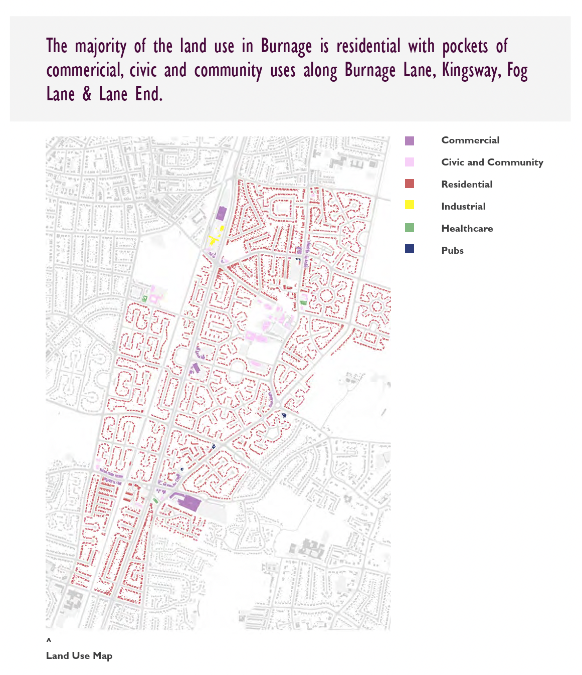
Land use in Burnage
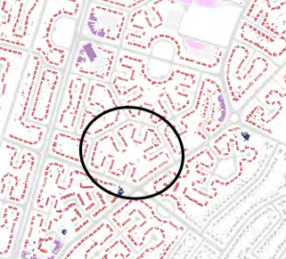
The avenue I grew up in and where my mum lives

Burnage ethnicity map
In addition to looking at maps of Manchester, I also looked at maps of Iran. Including the outline of the whole of Iran and the capital, Tehran.
I looked on my Ancestry DNA account at where specifically my DNA is from in Iran. This says my heritage is from North Central Iran and Central Isfahan Province. I found this really interesting as Isfahan is known for its incredible Persian architecture and is also the major centre fir traditional crafts in the country.

Outline of Iran

Outline of the capital city, Tehran
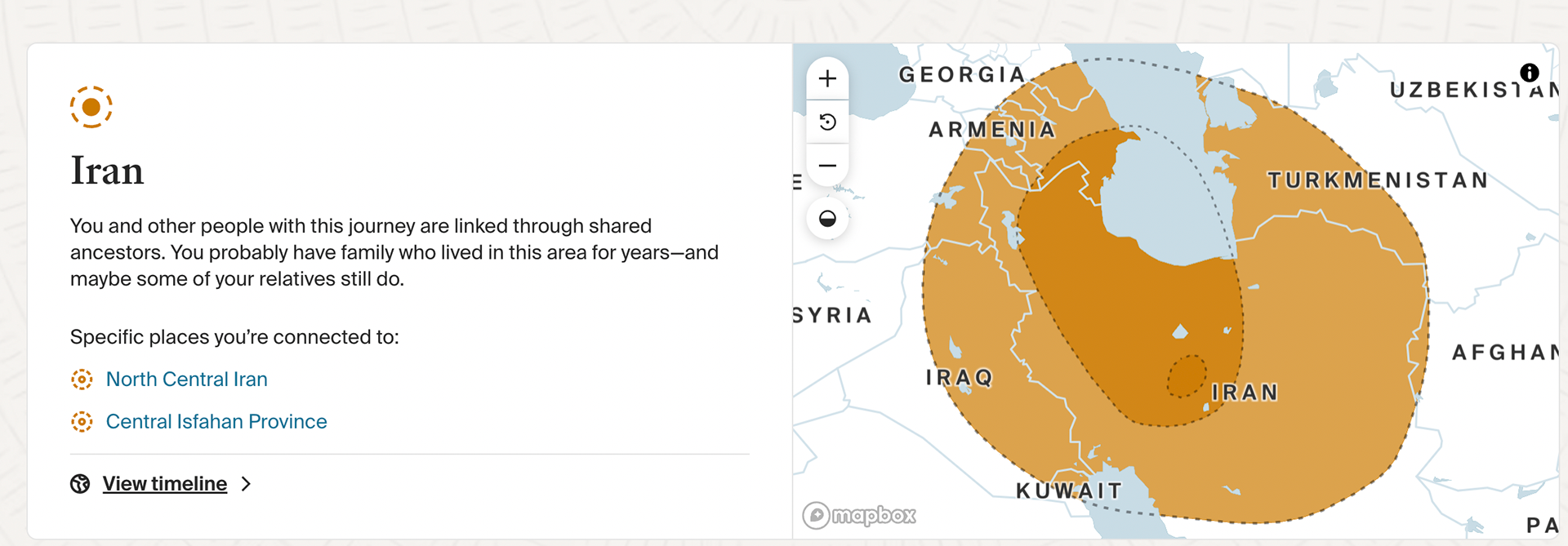
Ancestry data of where my DNA is from

Outline of Isfahan
Battoulah - Southern Iranian Masks
-These masks are worn in Southern Iran by the 'Bandari' women. These are women from the Hormozagab Province. People here are from a variety of ethnicities, including African, Arab, Indian and Persian.
The locals here wear different attire than locals in other areas of Iran.
The root of the tradition is unknown, however, it may come from when the Portuguese ruled Iran and pretty women would hide from slave masters.
They also protect the skin from sunlight
Similar masks are worn in Oman, Kuwait and other Arabian Peninsulas.
Some cover the whole face, while some cover less and show more eye area.
Usually made from leather or embroidered fabric
Different patterns and colours represent status and origin.

Masked Southern Iranian Woman

Masked Southern Iranian Woman
Brooch Pin Inspiration
The brooch I made for Unit X, unfortunately, didn't function as I had various problems with the brooch pin. I hadn't thought properly about this area of the design and hadn't done any test pieces to test the functionality of the pin. This is something I aim to do for my final project.
I have looked at various brooches on Instagram as I have been unable to get the 'To the Point' book from the library. I will test some pin designs before using it on my final brooch.

By Danielle Embry

By Beth Anderson

By Todd Conover

By Eva Kerer
I used 1mm steel wire for my previous brooch. However, I found this difficult to work with for my design. I have looked into the cost of Gold pin wire on Cookson's as well as looking at using Gold filled wire which is massively cheaper.
The gold-filled is half hard, and the base metal is Brass. I will order some of this to test the strength and durability of this and if it will be suitable in my designs.
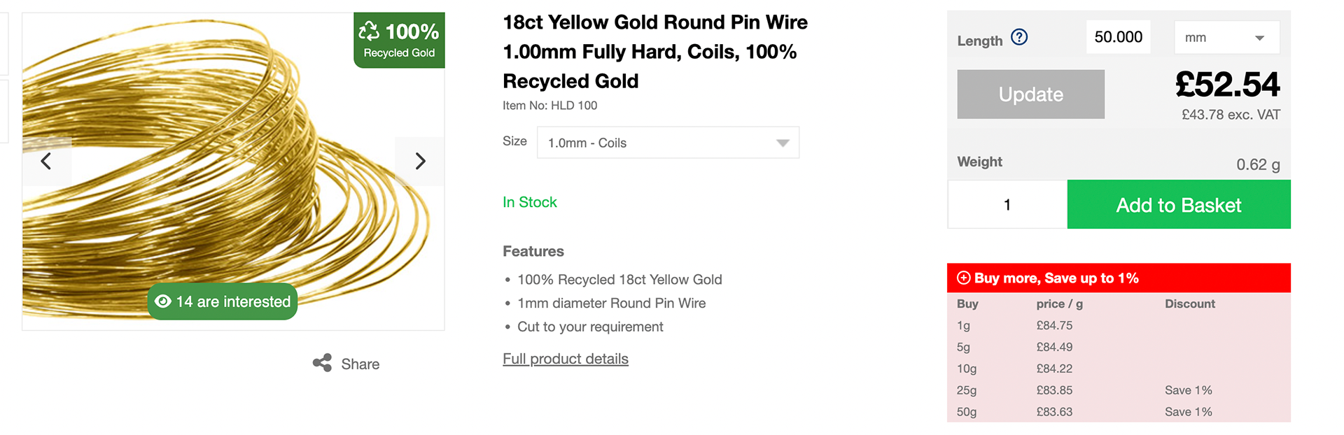
Solid gold pin wire prices for 5cm
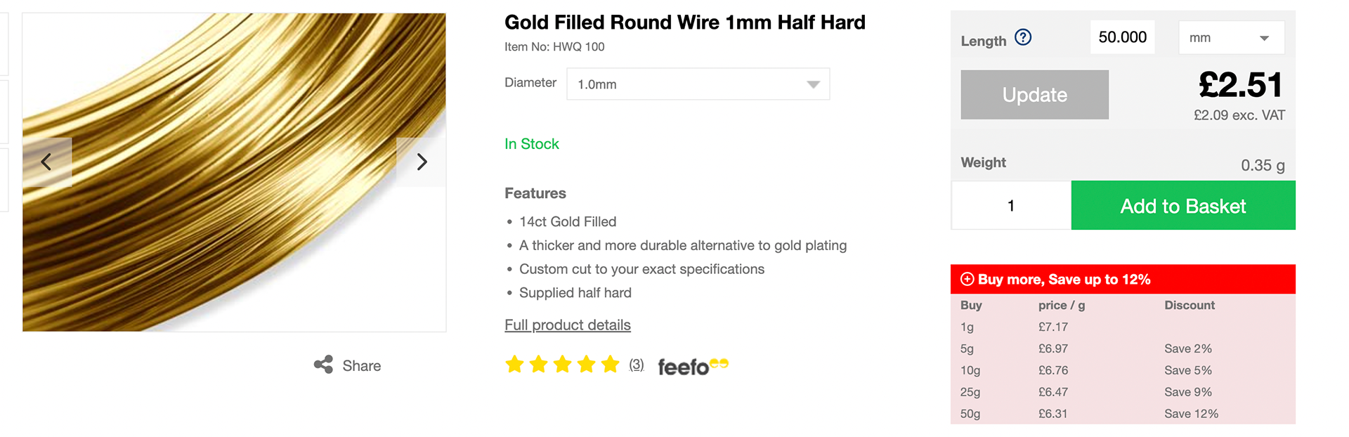
Gold filled wire prices for 5cm
Brooch - Making Samples
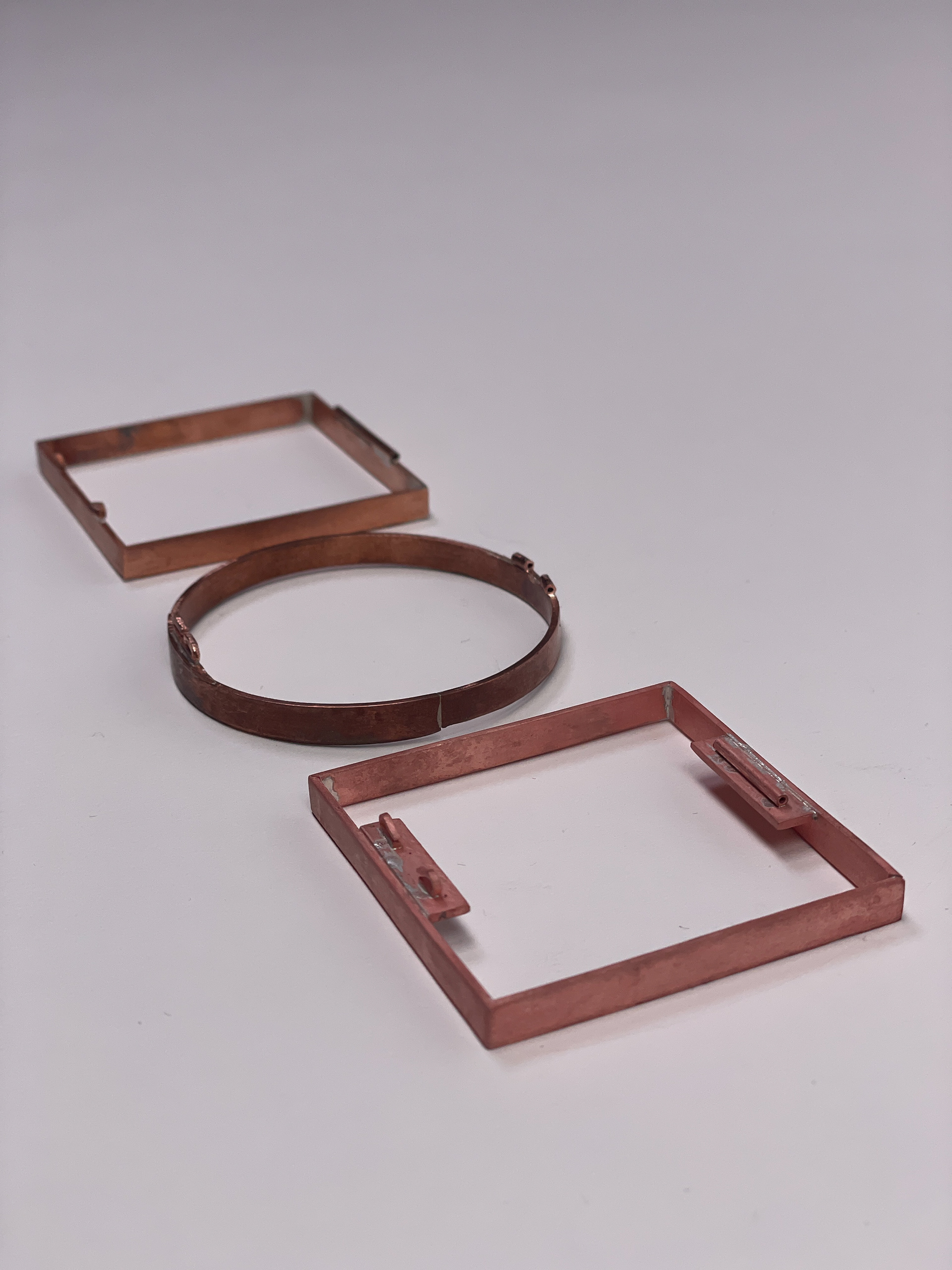
After having some thought about my idea and discussing my work with Patricia, I decided that creating a brooch, ring, and headpiece would be too much work for what I wanted to achieve in the time I had. Instead, I decided to make a series of brooches with different variations on them so that I could focus on developing them to a better standard.
I started looking at using the core shapes used in Persian geometry as the form for my Brooch. Previously, I felt I had overcomplicated designs and going forward, I wanted to try and simplify them. These are circles, squares, and triangles. I started with a circle, creating a bezel and soldering it onto sheet copper. I used the band saw to cut the excess sheet off however, I got too close to the bezel and took some of the metal off. To be more refined, I need to be more precise and careful at this stage.

Strip pf copper

Soldered to ring

Adding bezel to sheet

Soldered to sheet

Ready to be pierced

Pierced and filed
Overall this went reasonably well, but could be better for my next attempt by being neater with filing and using the band saw.
Next, I tested a few different attempts at creating a square shape. Test 1 involved soldering individual sides to the 2D square however, this was a disaster and won't work to get the accuracy I want.

Square sample 1

Soldered pieces

Side view

View from above showing unaligned joint
The second test piece was to score the edges and ben and solder them. This also didn't turn out very well. At this point, I realised I always go back to box-like forms, and they are never as accurate as I want.

Square sample 1 & 2

Sample 2 using scored lines to create 3D shape
Despite this, I attempted another method. This was to create a bezel like I did with the circle. I did this by cutting a 200mm x 5mm strip on the guillotine scoring lines at 50mm and filing 90-degree edges. However, the first attempt was ok but the angle of the edge wasn't 90 degrees and it wasn't very square. I attempted doing it another couple of times and got better each time however it wasn't perfect.

Strips to create bezel

Scored strips ready to bend

Checking if 90 degrees

Finished bezels
After doing this and reflecting. I had an idea of instead of scoring at 3 x 50mm sections and joining the shape on the corner. Instead, score at 25mm the 2 x 50 mm and soldering on the straight edge which is easier. This will also mean all the corners are equal which should help with the square being accurate.
The images below are square bezels I made by scoring at 25mm and 2x 50mm method.

Square bezels

Square in right angle tool

Square in right angle tool

Square in right angle tool
After making these using this method, it helped with getting the square more accurate. However, I found that the straight edges were not straight, so the metal didn't completely meet when it came to soldering, meaning filing the edge, therefore taking off length from the measurements. To correct this, I will make sure to cut these more accurately as the strips I used were made without focusing on accuracy as I made these quickly for previous tests.
In addition to this, the corners aren't as sharp as I would like. However, when shaping the square after soldering, the workshop doesn't have a stake the correct size that will benefit me most. There are also gaps in the corners, which I am going to try to avoid by using a different file.
Oxidising Samples
I decided my brooch would look nice being black. Black and Gold colour combination is a favourite of mine. In particular, Gold jewellery has a prominent feature in my life, as I only wear Gold and my mum does to which is where I got this taste from. The Black oxidation will also bring out the blue from the enamel. I conducted some tests using Platinol. I made a mix of 500ml water and a splash of the solution. I timed each strip for different lengths of time to see the result. These pieces of copper were shiny before oxidising, resulting in a black/brown shiny finish.
I noticed when taking the pieces out of the solution using plastic tweezers this would mark the metal so I knew on my final piece to resolve this by suspending the piece in the solution using string. As well as this, to make sure the piece is scratch free before hand and these also show when oxidised.

Oxidised samples on shiny copper

Test notes

Oxidised pieces on sandblasted copper

Test on plique a jour piece

Further oxidisng tests to get black colour

test notes
I then decided I wanted the black to have a matt finish so that the shiny enamel would stand out more. I tested sandblasting the copper first and then oxidising for a greater length of time to see the results whilst also using a stronger solution. The colour of oxidising in these pieces is what I wanted to achieve however I need to find a way to put the piece into the solution without any scratches.
Guild of Enamellers
Throughout last year, I joined the Guild of Enamellers and have been going to sessions they host when I can. These benefit me as the women there are very experienced with enamelling and advising me. I recently attended a session and showed Jill, who particularly knows about Plique à Jour, the pieces I have been doing. I was concerned about the clarity of the enamel due to using Copper however, Jill reassured me that she thinks I have done well with how I have progressed my skill level, and she said the Copper will only affect the black ring at the edge of the enamel. She gave me some tips to get better clarity, which I am going to test. However, she said I have done an amazing job so far.

Me with other guild members

Class sheet

Test pieces with other colours

Combining colours
This feedback from people who are experienced with enamelling was very reassuring for me and helped me believe in my skills more and made me want to strive to become better at this technique.
Pin Research - Behind the Brooch
These are images from the book Behind the Brooch by Lorena Angulo. I found this book useful to look at the importance of the back of a brooch as well as the front of it.


Pin Samples
In Unit X, I didn't do tests and samples of the mechanisms of my Brooch. This resulted in the Brooch pin not working and damaging the Brooch itself. Going into Synthesis and Resolution, I wanted to make sure I tested each part before making the final piece. I soldered a group of bezels together into rings to practice and test different brooch pins.

Pin Sketches

Pin Sketches

Soldering the rings

Solder lines

Cleaned up
In sample 1, I wanted to use a Copper tube. However, this meant I had to use 0.8mm wire for the pin. I tested this with Copper but I knew it would be too soft. After speaking with Patricia, she said I could use 0.7 or 0.8 mm steel wire instead. This piece didn't work, as I soldered the hooks the wrong way around. Reflecting on this design, I know where to make a few tweaks for it to work better.
Sample 2 I soldered hooks on the top of the bezel to attach a pin above. I also soldered these the wrong way at first however I changed this and attached a pin.

Sample 1

Sample 1

Sample 1

Sample 2

Sample 2
The next sample involved drilling holes in the bezel to attach the pin. This was my favourite way to attach as the holes will also benefit me when Oxidisng my piece due to being able to thread string through these. The shapes of the pins themself do work however I think I have overthought them and want to keep the design of this some simple.
In addition to this, I used 0.9mm Brass wire which I think with the right tension is strong enough. Steal would be better however I want the pin to have a gold colour to it against the black as this is a reflection of my personality and I prefer this colour combination. The Gold filled wire I have looked at has a base metal of Brass too.


Sample 2

Sample 3
Following this, I made some more sample brooch pins. The Brass wire is 0.9mm, and the Steel wire is 0.8mm. I used various methods, such as using a tube or drilling holes in the bezel. These worked well and helped me to get a better understanding of what's needed in a brooch pin and what I should avoid. the steel wire is better for functional purposes however, I would like the pin to be Gold.

Brooch pin I like

Brooch pin I dont like

Brooch pin I like
Pin to the left and right I prefer
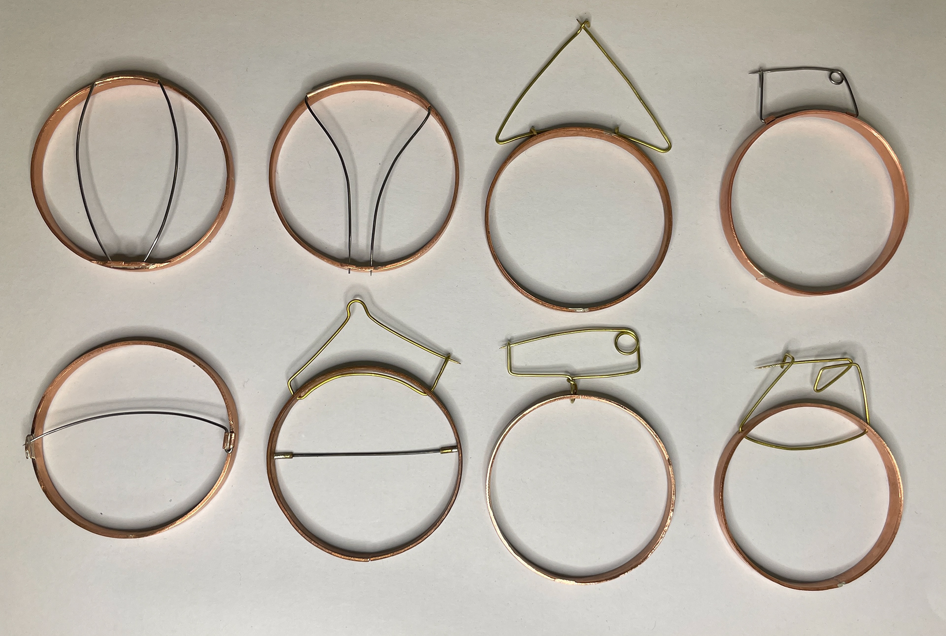
All brooch pin samples
In reflection of these samples, I prefer the simpler pins and know which work better than others. I want a combination of pins above the piece and also behind the piece.
Applications

I have applied for the Class of 2025 Open Call opportunity to be featured in a-n's Degree Show Guide. Unfortunately, I didn't get selected.
I have applied to attend this course on Brooch Pin Backs by Daniela Malev in Berlin. I believe this will be incredibly beneficial for my practice and gaining a better understanding of the importance of the back of Brooches and how to make them successfully.
Further Testing
I decided to do various other tests as I want to cover all areas before making my final piece. First, I tested solder joints as I use silver solder on copper and how this would react with the oxidising process. I put solder onto a piece of copper and sandblasted it, and then oxidised it. Followed by another piece of copper with silver solder on that I added to the contaminated pickle to turn the solder to look like copper, followed by oxidising. The results of these were both successful, and the solder was oxidised the same as the Copper sheet.
After looking at my Plique à Jour sample pieces, I noticed that some of them still had glass on the copper after I had ground off the excess glass using a diamond rotary tool bit. I decided to oxidise this as I thought it would be interesting, and the results were nice. Besides being able to see the grinding marks, I like that where the glass is left on top of the copper, you can see the tarnished metal underneath. There is something about this which is interesting, and I think I will test it more. I see it as a reflection of not forgetting where I grew up, Manchester. The copper tones coming through remind me of the red brick throughout Manchester architecture.

Pieces oxidising using string

Silver solder on copper

After sandblasting

Put in pickle with steel to make solder Copper plated

After oxidisng

Oxidisng enamelled piece

Solder joint not visible

After oxidising

After oxidising

Adding brooch pin

Brooch tube broke
Brooch pine

Brooch pin mechanism
Following these tests, I then decided to test all of the above on a brooch pin sample. I put the piece in contaminated pickle followed by oxidising, which worked really well. However, when attaching the pin, the tube came off, so the pin failed. This was a new style of pin I tried; however, I think if I were to try the straight pin again, I would have to use two pieces of tube to make the mechanism stronger. However, I do like the simplicity of this pin.
Final Square Brooch Tests
After attempting to make a perfect square using various methods and reflecting on what was going wrong, I knew I needed to get more accurate 45-degree angles. You can use a Jig, as shown below, to help do this; however, this is quite expensive. I spoke to the technician about making my own, which Paul guided me through as I had not used the tools needed for this before. I got a piece of steel and used the horizontal band saw to cut a 90-degree and 45-degree angle through the piece. I also used the pillar drill to drill down the steel to be able to attach the screws and bolts.
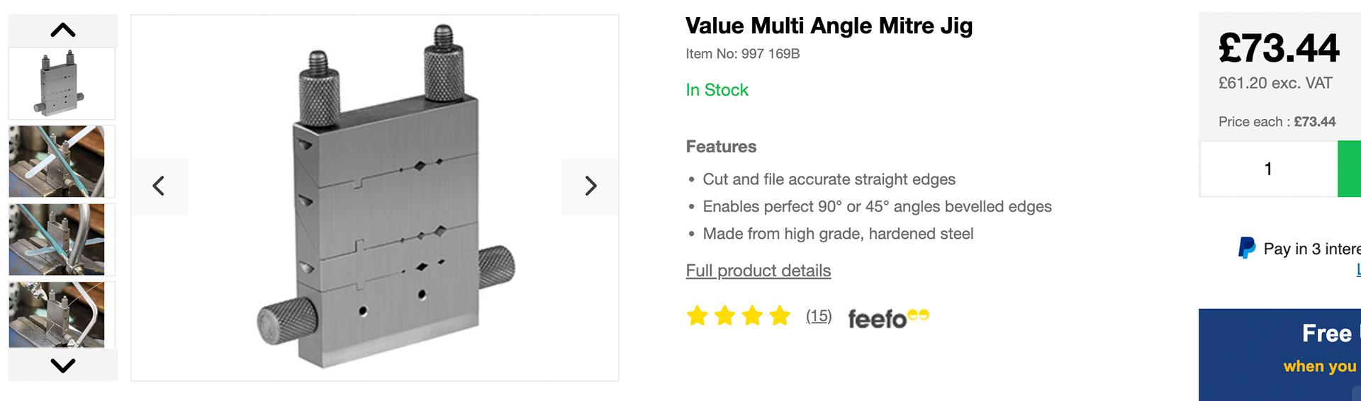
Mitre Jig sold on Cookson Gold

Horizontal bandsaw cutting steel block

Drilling holes for the screws

Holes after drilling

Horizontal band saw cutting 45 degree angle

finished tool

side view of finished tool
After researching and watching a YouTube video on creating a perfect square, I practiced using the tips I found. One method was to join the square at the side of the piece rather than at the corner. This is to make sure each corner is the same, reducing less risk of any difference in length by joining at the corner. Unfortunately, when I did this, the piece snapped by accident. I did manage to solder this still, but it was a mess. However, I know to be more careful with this going forward.

Ready to cut through to create even joint

Piece broken off

Using jig to cut 45 degree angle

Leaving a gap to make sure edge starts at the right length
I then also practised joining the square at the corner on a 45-degree angle. This was successful, and I managed to make a precise square as shown in the engineer's square tool.

Badly soldered joint

Badly soldered joints

Better joint but not perfect

45 degree angle joint

Soldered square fitting in 90 degree angle

Soldered square fitting in 90 degree angle

Soldered square fitting in 90 degree angle

Soldered square fitting in 90 degree angle
By researching and practising this, I gained a better understanding of how to accurately make a square. This is something I have struggled with previously and gave up trying, however, I decided to give it another go and was successful on this test piece.
Further Pin Development
After testing pin designs previously, I had an idea of what would and wouldn't work. I come up with new designs, including adding more of a platform for the mechanisms to be on, so that there is room for the length of the pin to sit without it overhanging from the edge of the brooch. I also made sure the pins are straight and parallel, as I learnt this is important with brooch pins if there are two of them. In addition to this, I learnt to shape the pin like a pencil using a grinding stone and making sure to polish the pin too.

Pin mechanism sketches

Using steel scrap to hold piece in place to solder
Brooch pin mechanisms
Brooch pin mechanisms

Point of pin

Brooch pin samples
Sketches
Based on previous research on the map contours of Iran and Manchester, I drew some sketches overlapping the map lines from both parts of my heritage. I like the simplicity of these and can see them working well with the Filigree work I have previously experimented with by using these map lines as a starting point to develop Filigree with my personal spin on the traditional technique.

Sketch 1

Sketch 2

Sketch 3

Sketch 4
Filigree Experimentation & Development
Despite changing my mind about what jewellery pieces I wanted to create, at this stage, I still wanted to incorporate filigree into some of my brooch designs and continue with the concept of having a combination of delicate and complex elements. I started by taking some wire and soldering it together to make a hoop. After this, I used various pliers to bend and sculpt the wire by looking at it and referring back to my sketches. The solder joint is visible if looked at closely and is something I will work on cleaning up and making less visible.

Soldered hoop

Shaped wire inspired by map contours

Close up on solder joint
Below, I bent the flat wire piece to sit into the edge of the Brooch form, including it folding over onto the front of the Brooch. From this, I knew where the piece would attach to the brooch, which meant I could now consider how to attach it.

Formed wire piece

Wire formed around Brooch

Considering where to attach wire

Considering where to attach wire

Considering it against the matte black

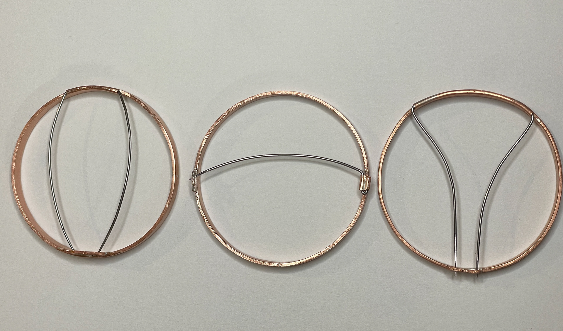
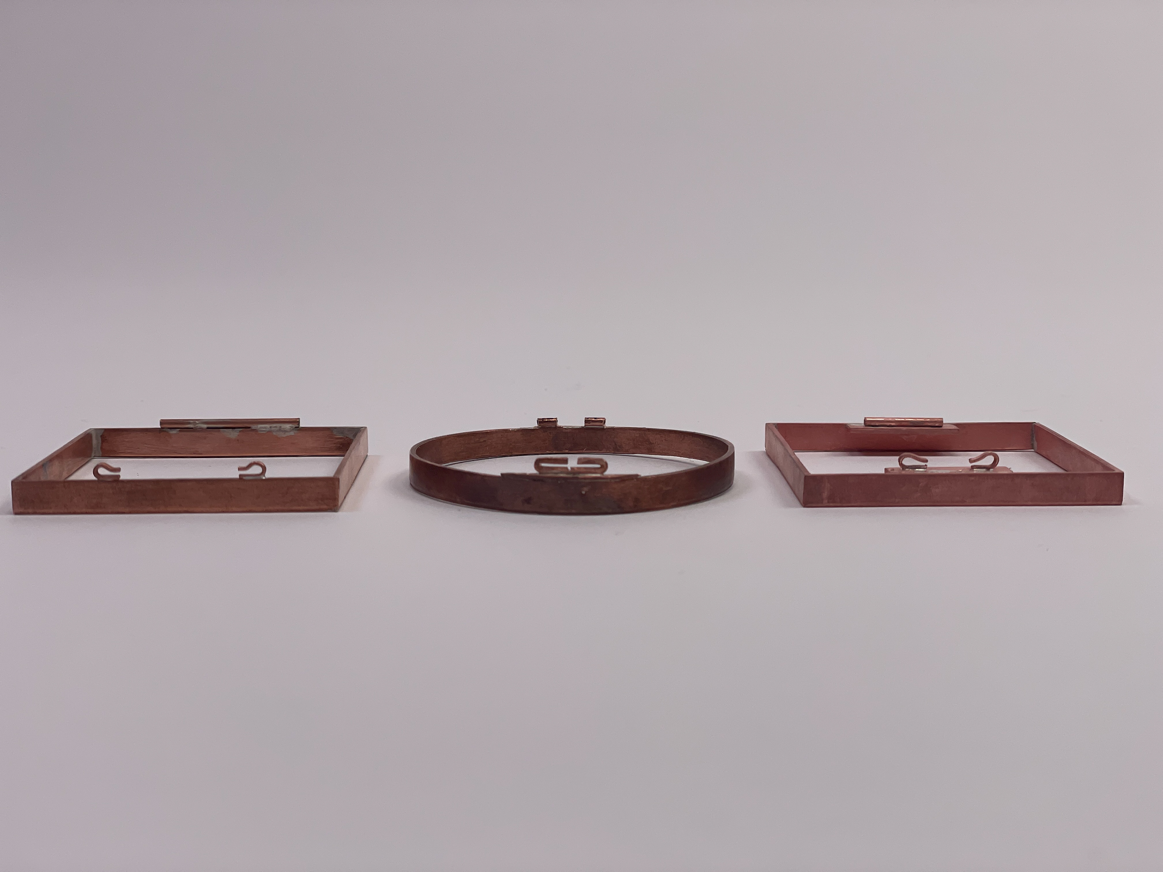
I made two samples of the middle and right sketches. However, the hook I used didn't work as I wanted because when the wire was secured, it was loose. However, the other mechanism was where I drilled a [ADD HOLE SIZE] hole and pierced a line so that the wire would fit snug into the hole and then be held in place by closing the mechanism shut with pliers. This was successful, as shown in the photos below. This is a discreet way to attach the wire piece so that it blends into the rest of the brooch.

Sketches of attachment ideas

Hook style attachment sample

Middle attachment style

Middle attachment style
After this, I decided to experiment with 0.4mm copper wire to have a more delicate aesthetic to the wire work. I used inspiration from the map lines of Manchester as well as the residential markings of where I grew up, Burnage, for the forms of these wires. I soldered these using the pick solder method to create less risk of melting the wires.

soldering 0.4 mm wire

soldering 0.4 mm wire

Soldered wires inspired by resident maps

Wires in the pickle
After cleaning the wires in the pickle, I then soldered them to the other wire to create a combination of sizes. I then attached this to the test mechanism to see how this would look. I then decided to experiment by adding multiple individual map lines, overlapping them onto the front of what would be the final brooch piece.

Wire piece after soldering 0.4mm wires

Wire piece after soldering 0.4mm wires

Piece attached using preferred mechanism

Piece attached using preferred mechanism

Visualising against finished brooch

Considering overlapping different contours

Experimenting arrangments

Preparing wires for soldering
After reflecting on this experimentation, I decided not to go ahead with it as part of my final pieces. This was because I felt it was too late in the project to be adding this, and it was not being developed as well as I would like. The reason I left it later in the project was because I was struggling to find someone to gold plate the wire, so I didn't want to put the work in for this part of my project to then not be able to find someone to plate the pieces. I also felt that it was too much alongside the Plique á Jour and could be developed as a project on its own in the future.